Support Center > Chromatic Manual
Chromatic Manual

Please update your Chromatic’s firmware to the latest version to ensure your Chromatic is equipped with the latest features and bug fixes.
Welcome to Chromatic
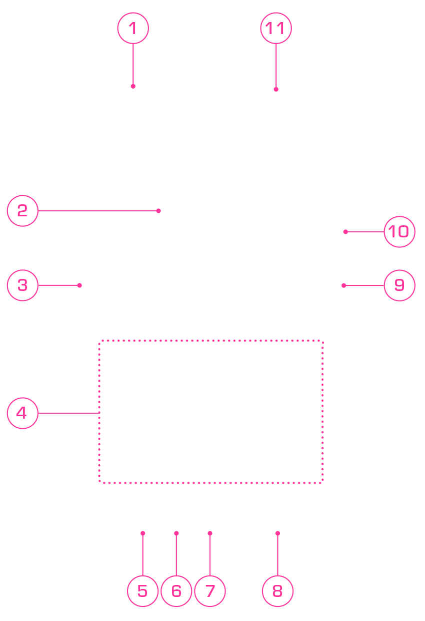
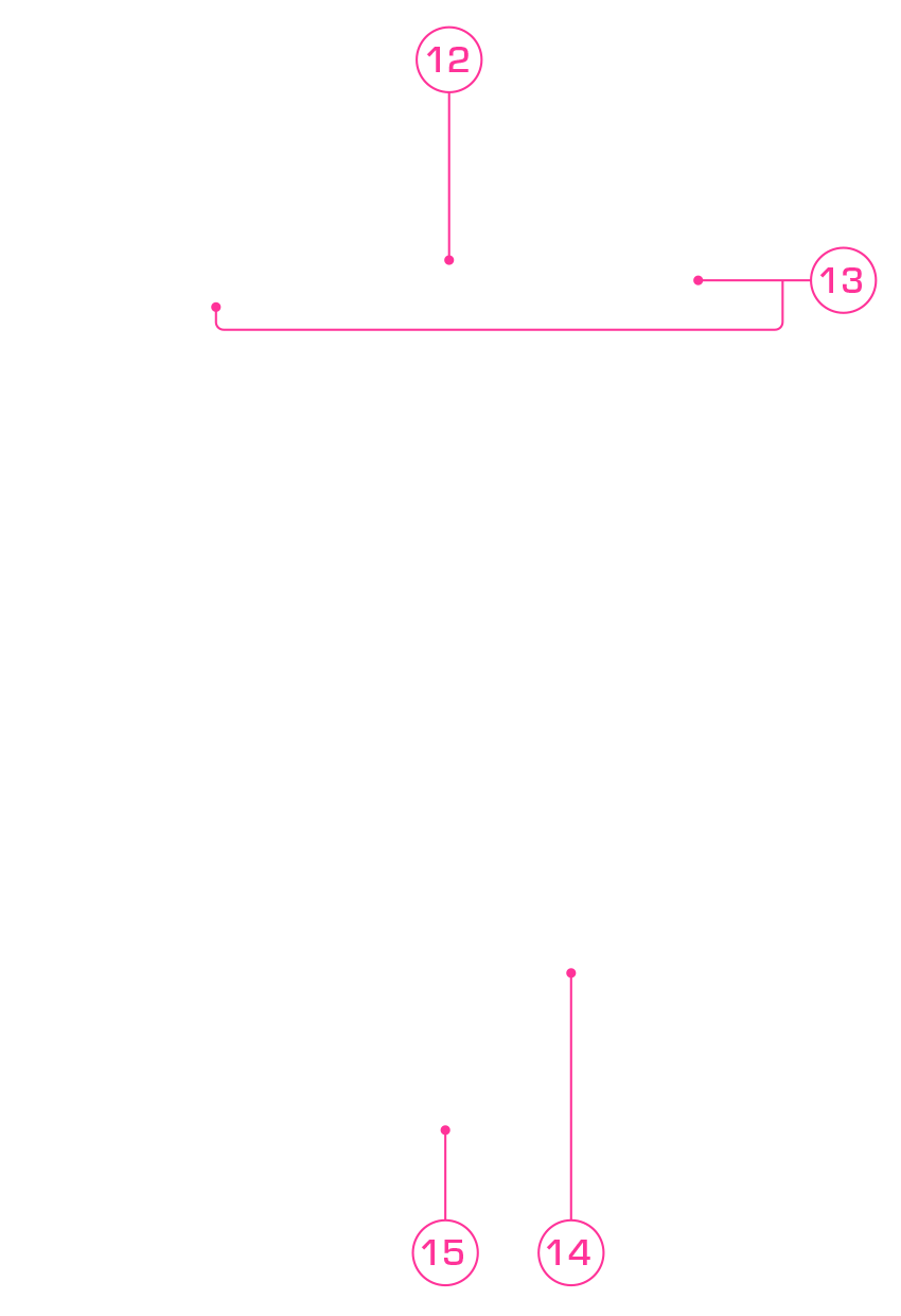
Chromatic can be powered using:
- USB-C direct power
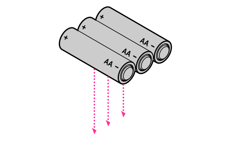
- 3 AA batteries
- Rechargeable Power Core lithium ion battery pack
Note: While connected via USB-C, the device operates on external power without depleting the battery.
AA Battery Installation

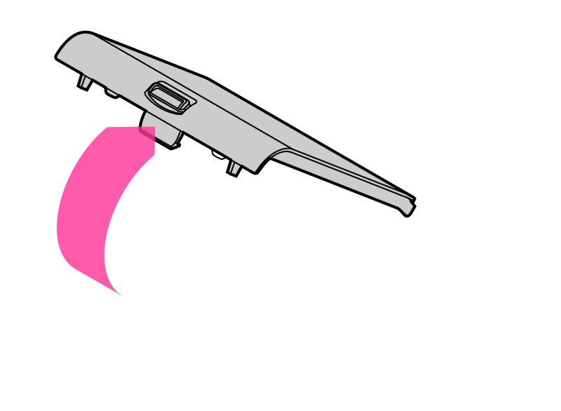
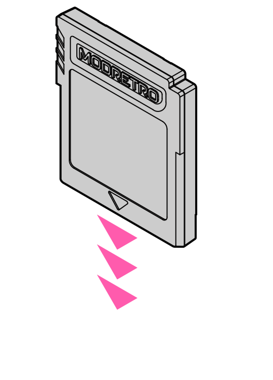
Make sure that the game label is facing away from Chromatic.
You should feel when the cartridge is fully seated.
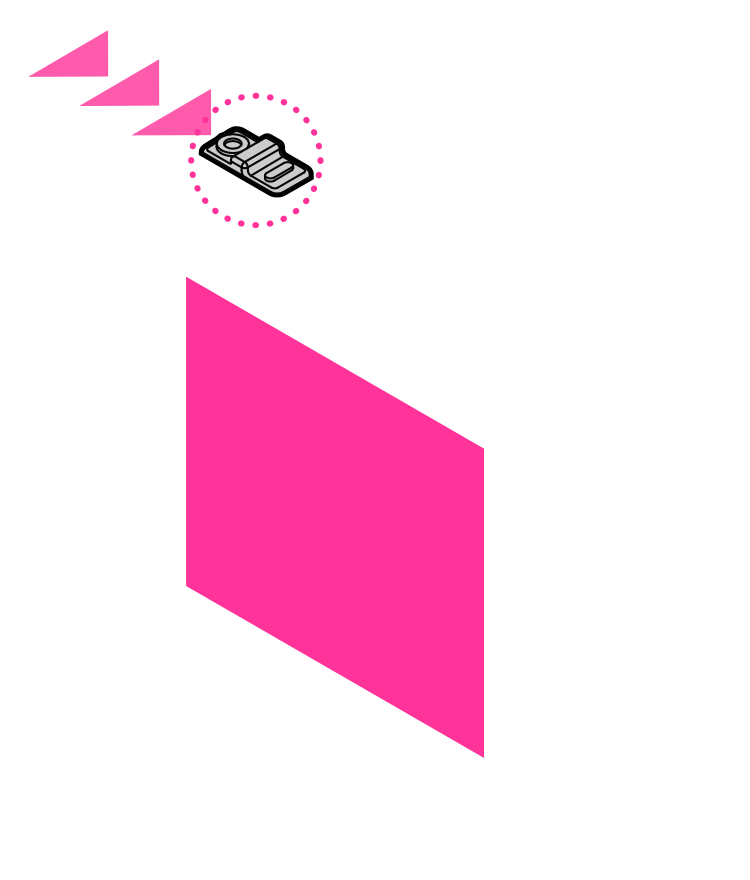
The LCD Display will illuminate and the game will load.
Follow instructions for the game you are playing.
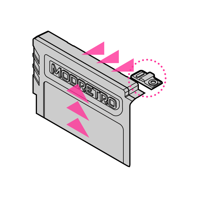
Then remove the cartridge by sliding it up.
The LED Indicator on the bottom of Chromatic displays the power status.

Displays change in power status when ON.
On for 5 sec when < 60%
Constant on when < 20%
Continuous blinking when < 5%
Displays charge status.
Charging in progress
Fully charged
The Infrared (IR) Port on top of the Chromatic allows for transmission of information between 2 systems (Chromatic to Chromatic or GBC) using games featuring infrared communication capability.
For optimal performance:
- Align the IR Ports with the systems between 1.5" - 2" (4cm - 5cm) apart.
- Do not use more than 2 systems at one time.
- Do not use in direct sunlight.
- Keep the IR Port clean and free of obstruction.
- Do not place objects between the IR Ports.
- Ensure battery power is not low.
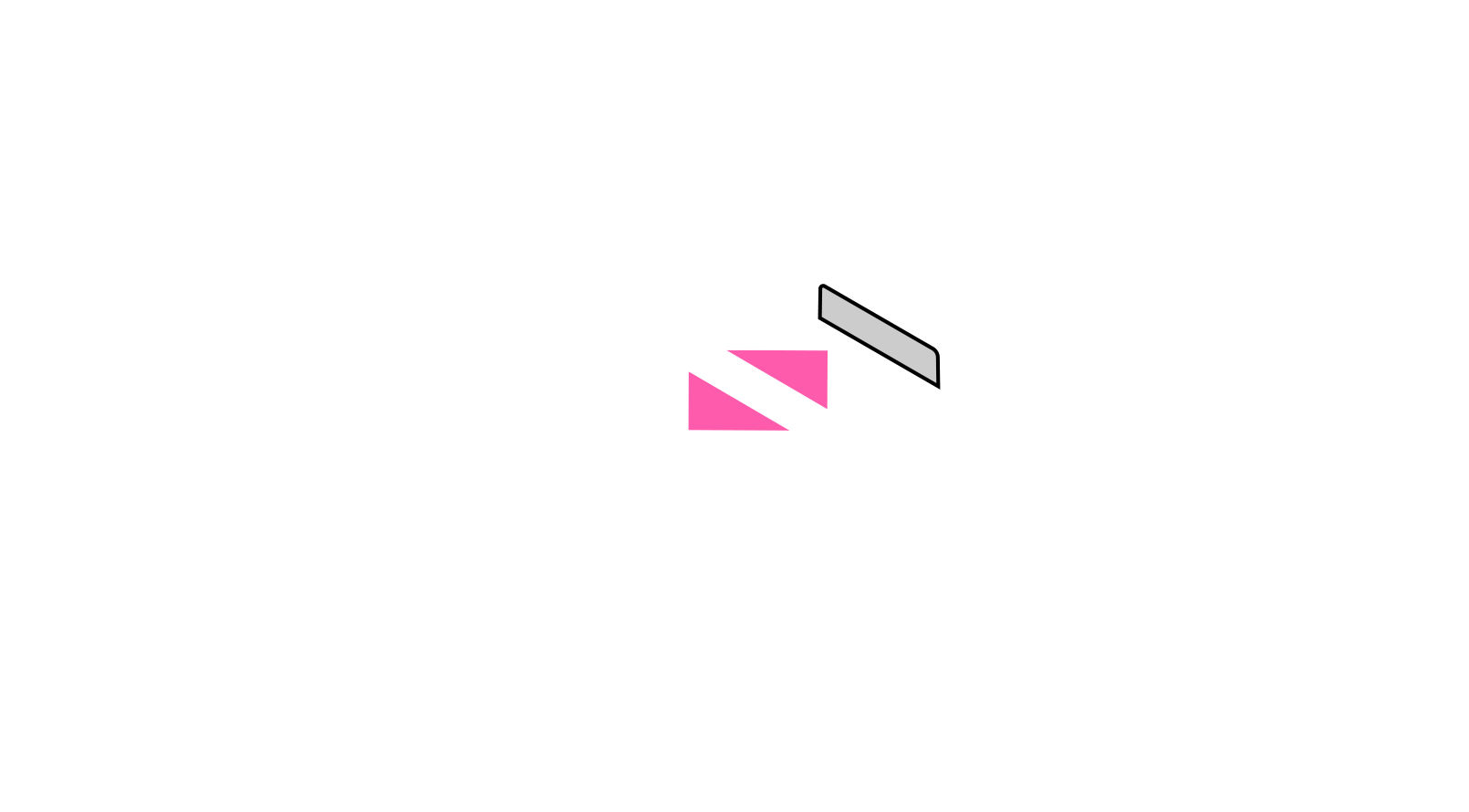
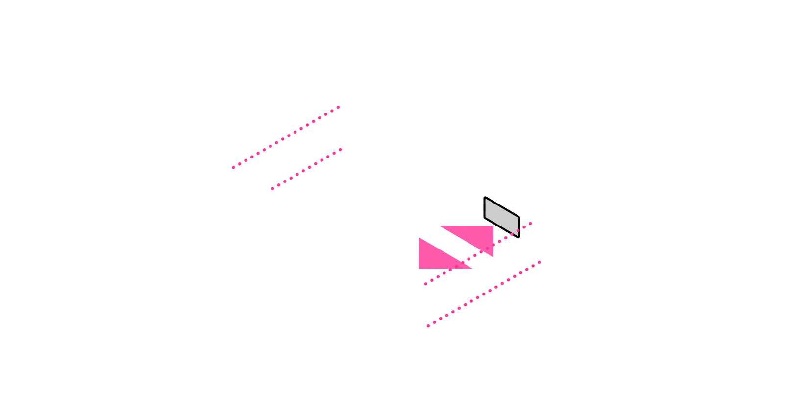
When using IR link between Chromatic and GBC, align the bodies of the systems. Do NOT center the IR windows to each other.
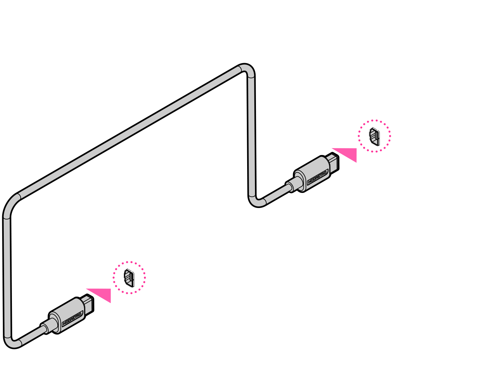
Games that feature a 2 player mode can be played using the Link Cable to connect 2 systems (Chromatic, GB, or GBC).
- Power should be OFF on all systems.
- Plug the Link Cable into the Link Cable Port of each system. Be sure the plug is fully inserted.
- Turn the power ON for both systems.
- Follow the game instructions for gameplay information.
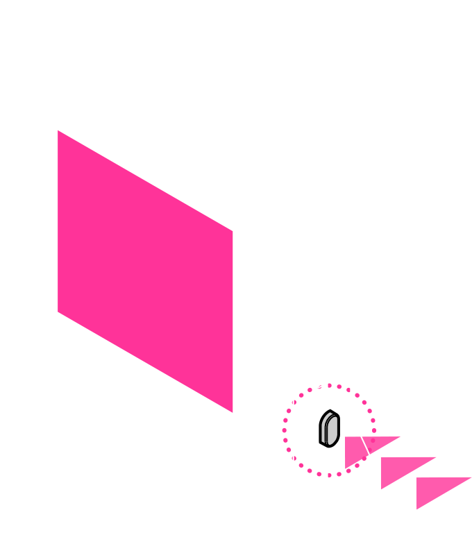
Please visit our blog post for detailed instructions on recording and streaming gameplay on your Chromatic.
Press the Menu Button to access system settings.
Note that entering system settings will not automatically pause gameplay.
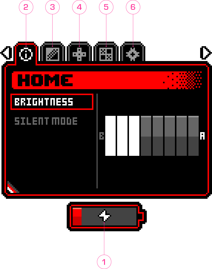
- Selecting a menu - Press left and right on the D Pad to highlight the menu you wish to make changes to.
- Changing settings - In the highlighted menu, press up and down on the D Pad to select settings displayed on the left side of the menu. Then press A to toggle settings on/off. For settings that allow for incremental adjustment, Press A to increase and B to decrease the setting.
- Exiting system settings - Press the Menu button to exit and return to gameplay.
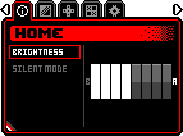
Brightness adjustment - Increase brightness by pressing A, decrease brightness by pressing B.
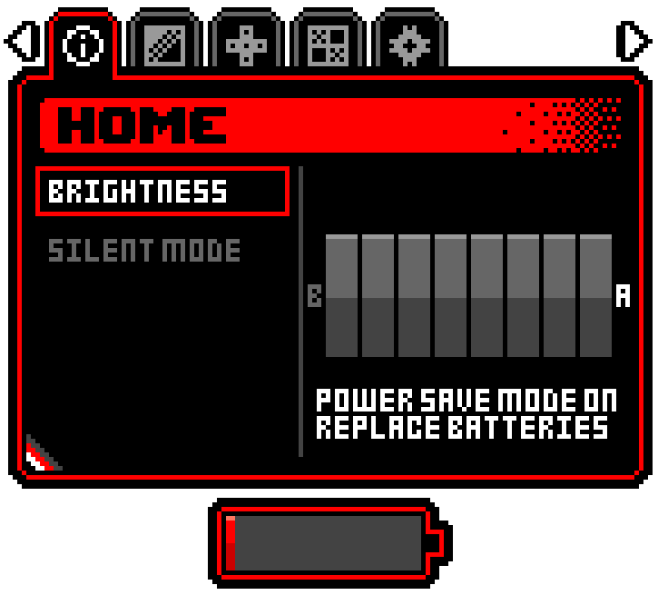
Power Saver Mode - When using nearly depleted batteries, Chromatic automatically enters Power Saver Mode. In Power Saver Mode, the brightness cannot be adjusted, and a message appears on the Home screen.
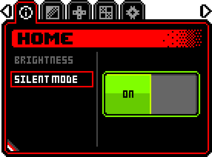
Silent Mode - Turns on/off device speaker and overrides the volume dial.
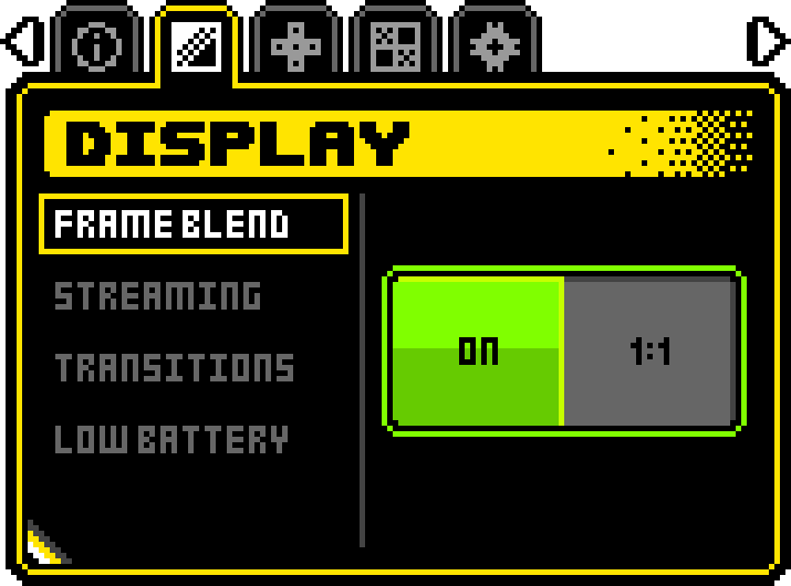
Frame Blend - For transparency effects on certain original GBC games.
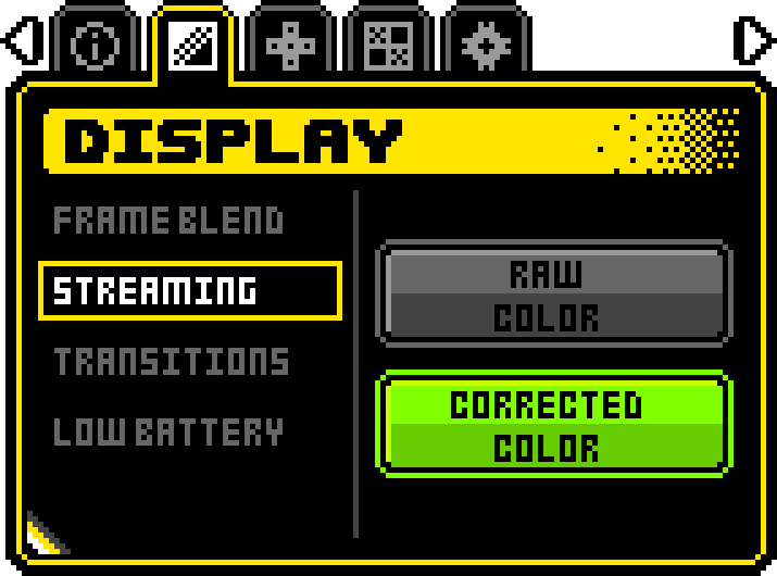
Streaming - Affects the display color when streaming.
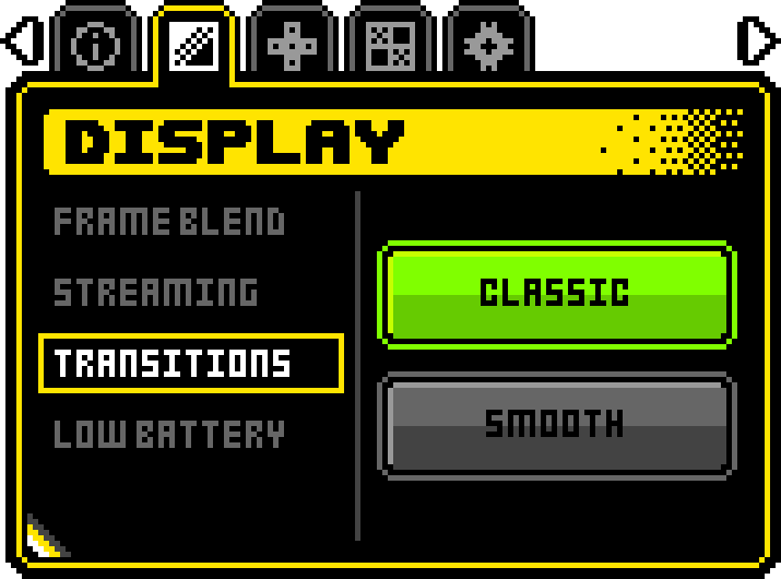
Some games will blank the game screen as part of their programmed sequence. On the classic DMG/GBC without a backlit screen, this appears as a white screen. On Chromatic (which is backlit), this appears as a flashing effect.
- Classic - Preserves the orginal behavior
- Smooth - Removes the flashing effect for a smoother experience
Note: This option may have no effect for many games.
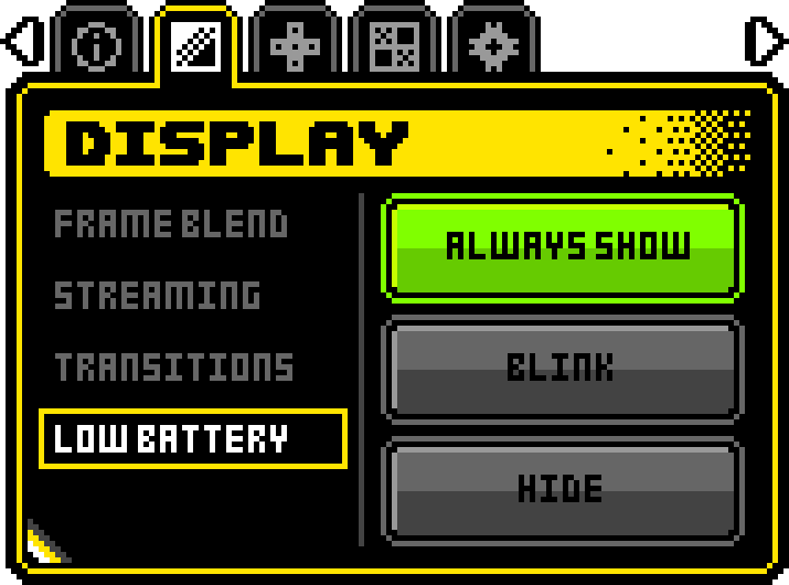
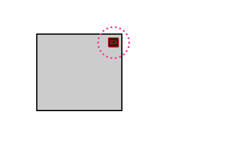
A low battery icon appears in the top-right corner of the screen when batteries are nearly depleted. For some games, this may obstruct gameplay.
- Always Show - Retain displaying the icon
- Blink - Icon will appear and disappear once per second
- Hide - Icon will be hidden. The user proceeds at their own risk.
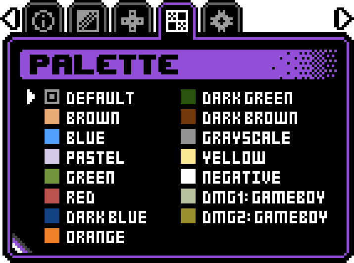
Select a palette with up and down.
Press A to save the selected palette. The saved palette is indicated by an inner rectangle. This will be loaded automatically the next time you turn on a game that supports this feature. A saved palette will override any palette selected via hotkeys, unless DEFAULT is saved.
Note: When DEFAULT is saved, the selector will automatically adjust to the default palette used by the game. As an example, Baby T-Rex defaults to Dark Green.
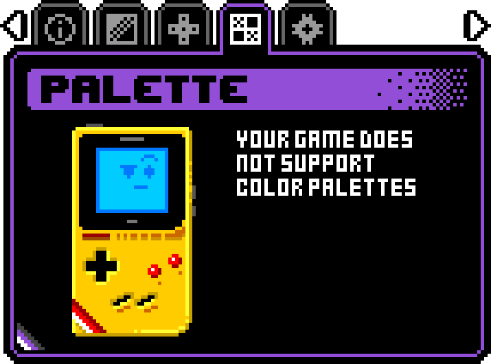
Palette selection is unsupported for GBC games.
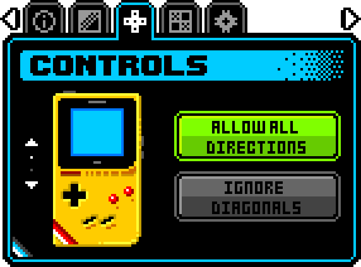
Allows modification of the D Pad behavior to ignore diagonal inputs.
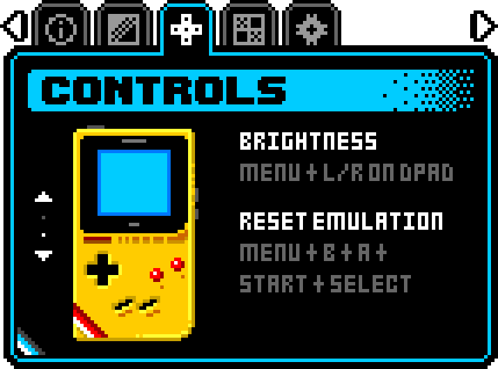
Displays available hotkeys.
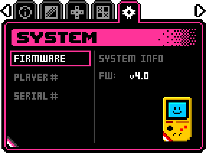
Firmware - Displays the firmware version the system is running. Pressing A on the FIRMWARE tab will display additional version information.
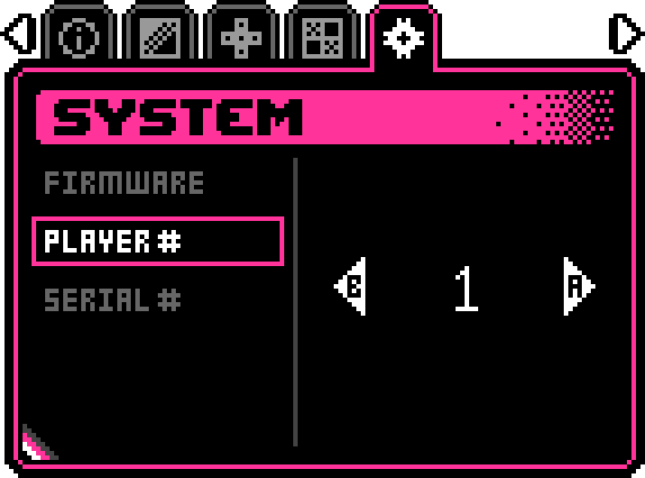
Player selection to set up a Capture Window.
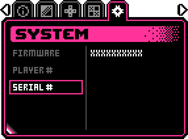
Displays the device’s serial number.
Hotkeys enable quick access to common features without navigating the System Settings menus. They also allow access to options not found in the System Settings. Note there are hotkeys that work On Boot and At Run-time. Please note that Game Boy Color® titles cannot use custom palettes.
For best results, press and hold the desired key combination(s) before turning on your Chromatic. Continue holding down the hotkeys until the screen illuminates.
If you manually change palettes using the Palette Settings menu, the following hotkeys are ignored.
- When using hotkeys, the Menu button will not open the System Settings interface.
- Hotkeys do not work while in the System Settings interface.
Troubleshooting
If a white screen appears when powering up a game, turn OFF Chromatic, remove and reinsert the game, and turn ON again.
If Chromatic is not operating correctly, turn the power OFF and back ON to reset the system.
If you are still having problems, please contact Customer Support.
Modifying Your Chromatic
Check out our step-by-step teardown of Chromatic here.
Games
GEN 1: The color coded sidebar on game boxes, cartridges, and instruction manuals indicates color and system compatibility.


GEN 2: The compatibility emblems displayed on the back of game boxes indicate system and accessory compatibility.
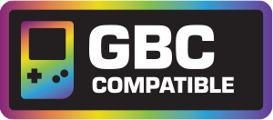


NOTE: Tetris is a GBC game, not a DMG game, and requires GBC-compatible hardware.
Compliance
Chromatic complies with the Low Voltage Directive (LVD), 2014/35/EU, Electromagnetic Compatibility (EMC) Directive, 2014/30/EU, and the Restriction of the use of certain hazardous substances in electrical and electronic equipment (RoHS) Directive, 2011/65/EU. For a copy of the official Declaration of Conformity, please click here.

Manufacturer: ModRetro, Inc.
15333 Culver Dr
STE 340 #2322
Irvine, CA 92604

